- 您现在的位置:买卖IC网 > PDF目录16484 > SI5365/66-EVB (Silicon Laboratories Inc)BOARD EVAL FOR SI5365/66 PDF资料下载
参数资料
| 型号: | SI5365/66-EVB |
| 厂商: | Silicon Laboratories Inc |
| 文件页数: | 9/28页 |
| 文件大小: | 0K |
| 描述: | BOARD EVAL FOR SI5365/66 |
| 标准包装: | 1 |
| 主要目的: | 计时,时钟发生器 |
| 已用 IC / 零件: | SI5365,SI5366 |
| 已供物品: | 板,线缆,CD,文档 |
第1页第2页第3页第4页第5页第6页第7页第8页当前第9页第10页第11页第12页第13页第14页第15页第16页第17页第18页第19页第20页第21页第22页第23页第24页第25页第26页第27页第28页
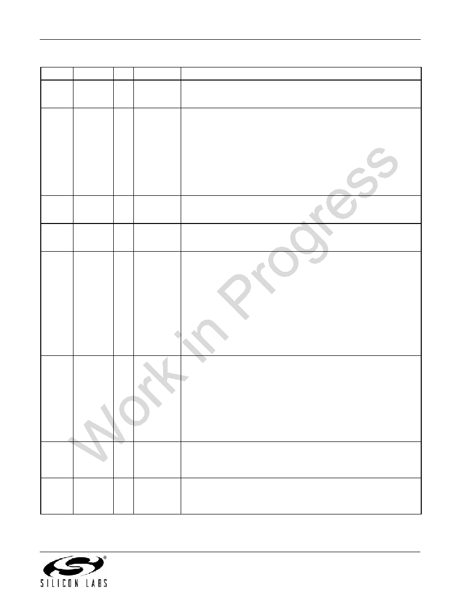
Si5365
Rev. 0.5
17
34
35
CKIN2+
CKIN2–
IMULTI
Clock Input 2.
Differential input clock. This input can also be driven with a single-
ended signal.
37
DBL2_BY
I
3-Level
CKOUT2 Disable/PLL Bypass Mode Control.
Controls enable of CKOUT2 divider/output buffer path and PLL bypass
mode.
L = CKOUT2 Enabled.
M = CKOUT2 Disabled.
H = BYPASS Mode with CKOUT2 enabled. Bypass is not available with
CMOS outputs.
This pin has a weak pullup and weak pulldown and defaults to M.
Some designs may require an external resistor voltage divider when
driven by an active device that will tri-state.
39
40
CKIN3+
CKIN3–
IMULTI
Clock Input 3.
Differential clock input. This input can also be driven with a single-
ended signal.
44
45
CKIN1+
CKIN1–
IMULTI
Clock Input 1.
Differential clock input. This input can also be driven with a single-
ended signal.
50
DBL5
I
3-Level
CKOUT5 Disable.
This pin performs the following functions:
L = Normal operation. Output path is active and signal format is deter-
mined by SFOUT inputs.
M = CMOS signal format. Overrides SFOUT signal format to allow
CKOUT5 to operate in CMOS format while the clock outputs operate in
a differential output format.
H = Powerdown. Entire CKOUT5 divider and output buffer path is pow-
ered down. CKOUT5 output will be in tristate mode during powerdown.
This pin has a weak pullup and weak pulldown and defaults to M.
Some designs may require an external resistor voltage divider when
driven by an active device that will tri-state.
56
FOS_CTL
I
3-Level
Frequency Offset Control.
This pin enables or disables use of the CKIN2 FOS reference as an
input to the clock selection state machine.
L = FOS Disabled.
M = Stratum 3/3E FOS Threshold.
H = SONET Minimum Clock FOS Threshold.
This pin has both weak pullups and weak pulldowns and defaults to M.
Some designs may require an external resistor voltage divider when
driven by an active device that will tri-state.
58
C1A
O
LVCMOS
CKIN1 Active Clock Indicator.
This pin serves as the CKIN1 active clock indicator.
0 = CKIN1 is not the active input clock.
1 = CKIN1 is currently the active input clock to the PLL.
59
C2A
O
LVCMOS
CKIN2 Active Clock Indicator.
This pin serves as the CKIN2 active clock indicator.
0 = CKIN2 is not the active input clock.
1 = CKIN2 is currently the active input clock to the PLL.
Table 6. Si5365 Pin Descriptions (Continued)
Pin #
Pin Name
I/O Signal Level
Description
相关PDF资料 |
PDF描述 |
|---|---|
| EMM11DSEH-S243 | CONN EDGECARD 22POS .156 EYELET |
| SI5322/23-EVB | BOARD EVAL FOR SI5322/23 |
| LBC2518T150K | INDUCTOR WOUND 15UH 285MA 1007 |
| GBM22DTBT-S189 | CONN EDGECARD 44POS R/A .156 SLD |
| 6754410-6 | CA,XG,MTRJ-SC |
相关代理商/技术参数 |
参数描述 |
|---|---|
| Si5365-B-GQ | 功能描述:时钟合成器/抖动清除器 PIN-PROGRAMMABLE CLK MULTIPLIER 5 OUTS RoHS:否 制造商:Skyworks Solutions, Inc. 输出端数量: 输出电平: 最大输出频率: 输入电平: 最大输入频率:6.1 GHz 电源电压-最大:3.3 V 电源电压-最小:2.7 V 封装 / 箱体:TSSOP-28 封装:Reel |
| SI5365-B-GQR | 制造商:Silicon Laboratories Inc 功能描述: |
| Si5365-C-GQ | 功能描述:时钟合成器/抖动清除器 PIN-PROGRAMMABLE CLK MULTIPLIER 5 OUTS RoHS:否 制造商:Skyworks Solutions, Inc. 输出端数量: 输出电平: 最大输出频率: 输入电平: 最大输入频率:6.1 GHz 电源电压-最大:3.3 V 电源电压-最小:2.7 V 封装 / 箱体:TSSOP-28 封装:Reel |
| SI5365-C-GQR | 功能描述:时钟发生器及支持产品 Pin-Progrm Precision Clk Xplier 4In/5Out RoHS:否 制造商:Silicon Labs 类型:Clock Generators 最大输入频率:14.318 MHz 最大输出频率:166 MHz 输出端数量:16 占空比 - 最大:55 % 工作电源电压:3.3 V 工作电源电流:1 mA 最大工作温度:+ 85 C 安装风格:SMD/SMT 封装 / 箱体:QFN-56 |
| SI5365-EVB | 制造商:Silicon Laboratories Inc 功能描述: |
发布紧急采购,3分钟左右您将得到回复。