- 您现在的位置:买卖IC网 > PDF目录298480 > 70T631S12DDGI (INTEGRATED DEVICE TECHNOLOGY INC) 256K X 18 DUAL-PORT SRAM, 12 ns, PQFP144 PDF资料下载
参数资料
| 型号: | 70T631S12DDGI |
| 厂商: | INTEGRATED DEVICE TECHNOLOGY INC |
| 元件分类: | SRAM |
| 英文描述: | 256K X 18 DUAL-PORT SRAM, 12 ns, PQFP144 |
| 封装: | 20 X 20 MM, 1.40 MM HIEGHT, GREEN, TQFP-144 |
| 文件页数: | 14/27页 |
| 文件大小: | 220K |
| 代理商: | 70T631S12DDGI |
第1页第2页第3页第4页第5页第6页第7页第8页第9页第10页第11页第12页第13页当前第14页第15页第16页第17页第18页第19页第20页第21页第22页第23页第24页第25页第26页第27页
21
IDT70T633/1S
High-Speed 2.5V 512/256K x 18 Asynchronous Dual-Port Static RAM
Industrial and Commercial Temperature Ranges
Functional Description
The IDT70T633/1 provides two ports with separate control, address
and I/O pins that permit independent access for reads or writes to any
location in memory. The IDT70T633/1 has an automatic power down
feature controlled by
CE. The CE0 and CE1 control the on-chip power
down circuitry that permits the respective port to go into a standby mode
when not selected (
CE = HIGH). When a port is enabled, access to the
entire memory array is permitted.
Interrupts
If the user chooses the interrupt function, a memory location (mail
box or message center) is assigned to each port. The left port interrupt
flag (
INTL) is asserted when the right port writes to memory location
7FFFE (HEX), where a write is defined as
CER = R/WR = VIL per the
Truth Table. The left port clears the interrupt through access of
address location 7FFFE when
CEL = OEL = VIL, R/W is a "don't care".
Likewise, the right port interrupt flag (
INTR) is asserted when the left
port writes to memory location 7FFFF (HEX) and to clear the interrupt
flag (
INTR), the right port must read the memory location 7FFFF. The
message (18 bits) at 7FFFE or 7FFFF (3FFFF or 3FFFE for IDT70T631)
is user-defined since it is an addressable SRAM location. If the interrupt
function is not used, address locations 7FFFE and 7FFFF are not used
as mail boxes, but as part of the random access memory. Refer to Truth
Table III for the interrupt operation.
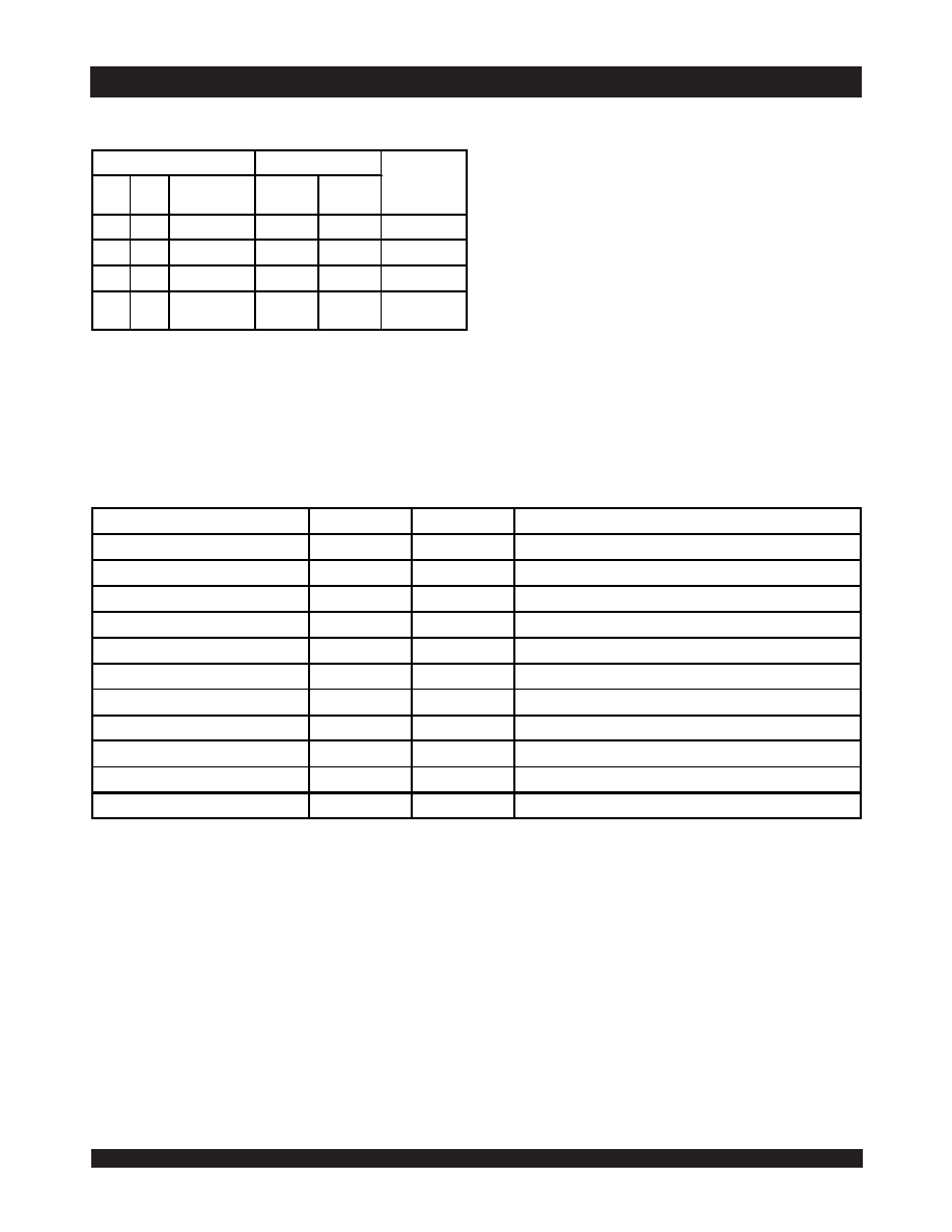
Truth Table IV —
Address BUSY Arbitration
NOTES:
1. Pins
BUSYL and BUSYR are both outputs when the part is configured as a master. Both are inputs when configured as a slave. BUSY outputs on the
IDT70T633/1 are push-pull, not open drain outputs. On slaves the
BUSY input internally inhibits writes.
2. "L" if the inputs to the opposite port were stable prior to the address and enable inputs of this port. "H" if the inputs to the opposite port became stable after the address
and enable inputs of this port. If tAPS is not met, either
BUSYL or BUSYR = LOW will result. BUSYL and BUSYR outputs can not be LOW simultaneously.
3. Writes to the left port are internally ignored when
BUSYL outputs are driving LOW regardless of actual logic level on the pin. Writes to the right port are internally ignored
when
BUSYR outputs are driving LOW regardless of actual logic level on the pin.
4. A18 is a NC for IDT70T631. Address comparison will be for A0 - A17.
5.
CEX = L means CE0X = VIL and CE1X = VIH. CEX = H means CE0X = VIH and/or CE1X = VIL.
Truth Table V — Example of Semaphore Procurement Sequence(1,2,3)
NOTES:
1. This table denotes a sequence of events for only one of the eight semaphores on the IDT70T633/1.
2. There are eight semaphore flags written to via I/O0 and read from all I/O's (I/O0-I/O17). These eight semaphores are addressed by A0 - A2.
3.
CE0 = VIH, CE1 = SEM = VIL to access the semaphores. Refer to the Semaphore Read/Write Control Truth Table.
Inputs
Outputs
Function
CEL(5) CER(5)
A0L-A18L
(4)
A0R-A18R
BUSYL(1)
BUSYR(1)
X
NO MATCH
H
Normal
H
X
MATCHH
HNormal
X
H
MATCHH
HNormal
LL
MATCH
(2)
Write Inhibit
(3)
5670 tbl 18
Functions
D0 - D17 Left
D0 - D17 Right
Status
No Action
1
Semaphore free
Left Port Writes "0" to Semaphore
0
1
Left port has semaphore token
Right Port Writes "0" to Semaphore
0
1
No change. Right side has no write access to semaphore
Left Port Writes "1" to Semaphore
1
0
Right port obtains semaphore token
Left Port Writes "0" to Semaphore
1
0
No change. Left port has no write access to semaphore
Right Port Writes "1" to Semaphore
0
1
Left port obtains semaphore token
Left Port Writes "1" to Semaphore
1
Semaphore free
Right Port Writes "0" to Semaphore
1
0
Right port has semaphore token
Right Port Writes "1" to Semaphore
1
Semaphore free
Left Port Writes "0" to Semaphore
0
1
Left port has semaphore token
Left Port Writes "1" to Semaphore
1
Semaphore free
5670 tbl 19
相关PDF资料 |
PDF描述 |
|---|---|
| 70V18L15PF8 | 64K X 9 DUAL-PORT SRAM, 15 ns, PQFP100 |
| 70V3319S166BFG | 256K X 18 DUAL-PORT SRAM, 3.6 ns, CBGA208 |
| 70V3319S133BCGI | 256K X 18 DUAL-PORT SRAM, 4.2 ns, CBGA256 |
| 70V9389L9PRFI8 | 64K X 18 DUAL-PORT SRAM, 20 ns, PQFP128 |
| IDT70V9289L9PRF8 | 64K X 16 DUAL-PORT SRAM, 20 ns, PQFP128 |
相关代理商/技术参数 |
参数描述 |
|---|---|
| 70T631S15BC | 制造商:Integrated Device Technology Inc 功能描述:SRAM Chip Async Dual 2.5V 4M-Bit 256K x 18 15ns 256-Pin CABGA Tray 制造商:Integrated Device Technology Inc 功能描述:SRAM ASYNC DUAL 2.5V 4.5MBIT 256KX18 15NS 256BGA - Rail/Tube 制造商:Integrated Device Technology Inc 功能描述:256K X 18 STD-PWR, 2.5V DUAL PORT RAM |
| 70T631S15BC8 | 制造商:Integrated Device Technology Inc 功能描述:SRAM Chip Async Dual 2.5V 4M-Bit 256K x 18 15ns 256-Pin CABGA T/R 制造商:Integrated Device Technology Inc 功能描述:SRAM ASYNC DUAL 2.5V 4.5MBIT 256KX18 15NS 256BGA - Tape and Reel 制造商:Integrated Device Technology Inc 功能描述:256K X 18 STD-PWR, 2.5V DUAL PORT RAM |
| 70T631S15BF | 功能描述:静态随机存取存储器 256K X 18 STD-PWR, 2.5V DUAL PORT RAM RoHS:否 制造商:Cypress Semiconductor 存储容量:16 Mbit 组织:1 M x 16 访问时间:55 ns 电源电压-最大:3.6 V 电源电压-最小:2.2 V 最大工作电流:22 uA 最大工作温度:+ 85 C 最小工作温度:- 40 C 安装风格:SMD/SMT 封装 / 箱体:TSOP-48 封装:Tray |
| 70T631S15BF8 | 制造商:Integrated Device Technology Inc 功能描述:SRAM Chip Async Dual 2.5V 4M-Bit 256K x 18 15ns 208-Pin CABGA T/R 制造商:Integrated Device Technology Inc 功能描述:SRAM ASYNC DUAL 2.5V 4.5MBIT 256KX18 15NS 208FPBGA - Tape and Reel 制造商:Integrated Device Technology Inc 功能描述:256K X 18 STD-PWR, 2.5V DUAL PORT RAM |
| 70T633S10BC | 功能描述:静态随机存取存储器 512K X 18 STD-PWR, 2.5V DUAL PORT RAM RoHS:否 制造商:Cypress Semiconductor 存储容量:16 Mbit 组织:1 M x 16 访问时间:55 ns 电源电压-最大:3.6 V 电源电压-最小:2.2 V 最大工作电流:22 uA 最大工作温度:+ 85 C 最小工作温度:- 40 C 安装风格:SMD/SMT 封装 / 箱体:TSOP-48 封装:Tray |
发布紧急采购,3分钟左右您将得到回复。