- 您现在的位置:买卖IC网 > PDF目录19188 > MMA6361LR2 (Freescale Semiconductor)IC ACCELER 1.5G XY-AXIS 14LGA PDF资料下载
参数资料
| 型号: | MMA6361LR2 |
| 厂商: | Freescale Semiconductor |
| 文件页数: | 5/11页 |
| 文件大小: | 0K |
| 描述: | IC ACCELER 1.5G XY-AXIS 14LGA |
| 标准包装: | 5,000 |
| 轴: | X,Y |
| 加速范围: | ±1.5,6g |
| 灵敏度: | 800,206 mV/g |
| 电源电压: | 2.2 V ~ 3.6 V |
| 输出类型: | 模拟 |
| 带宽: | 400Hz |
| 安装类型: | 表面贴装 |
| 封装/外壳: | 14-VFLGA |
| 供应商设备封装: | 14-LGA(3x5) |
BASIC CONNECTIONS
Pin Descriptions
Top View
PCB Layout
N/C
POWER SUPPLY
N/C
X OUT
Y OUT
N/C
GND
N/C
N/C
g-Select
V DD
V SS
Sleep
C
C
V RH
P0
V DD
V SS
C
V SS
V DD
N/C
N/C
g-Select
GND
P1
Sleep
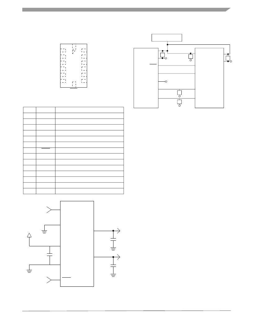
Figure 4. Pinout Description
Table 4. Pin Descriptions
Pin No. Pin Name
Description
X OUT
Y OUT
C
C
A/D IN
A/D IN
1
2
3
4
5
6
7
8
9
10
11
12
13
14
N/C
X OUT
Y OUT
N/C
V SS
V DD
Sleep
NC
N/C
g-Select
N/C
N/C
GND
N/C
No internal connection. Leave unconnected.
X direction output voltage.
Y direction output voltage,
Unused for factory trim. Leave unconnected.
Power Supply Ground.
Power Supply Input.
Logic input pin to enable product or Sleep Mode
No internal connection. Leave unconnected.
No internal connection. Leave unconnected.
Logic input pin to select g level
Unused for factory trim. Leave unconnected.
Unused for factory trim. Leave unconnected.
Connect to Ground.
Unused for factory trim. Leave unconnected.
Figure 6. Recommended PCB Layout for Interfacing
Accelerometer to Microcontroller
NOTES:
1. Use 0.1 μF capacitor on V DD to decouple the power
source.
2. Physical coupling distance of the accelerometer to
the microcontroller should be minimal.
3. Place a ground plane beneath the accelerometer to
reduce noise, the ground plane should be attached to
all of the open ended terminals shown in Figure 6 .
4. Use a 3.3 nF capacitor on the outputs of the
accelerometer to minimize clock noise (from the
switched capacitor filter circuit).
5. PCB layout of power and ground should not couple
power supply noise.
6. Accelerometer and microcontroller should not be a
Logic
Input
10
g-Select
MMA6361L
high current path.
7. A/D sampling rate and any external power supply
switching frequency should be selected such that
VDD
13
6
GND
VDD
XOUT
2
3.3 nF
they do not interfere with the internal accelerometer
sampling frequency (11 kHz for the sampling
frequency). This will prevent aliasing errors.
8. 10 M Ω or higher is recommended on X OUT , Y OUT and
Z OUT to prevent loss due to the voltage divider
relationship between the internal 32 k Ω resistor and
0.1 μF
5
VSS
YOUT
3
3.3 nF
the measurement input impedance.
Logic
Input
7
Sleep
Figure 5. Accelerometer with Recommended
Connection Diagram
MMA6361L
Sensors
Freescale Semiconductor
5
相关PDF资料 |
PDF描述 |
|---|---|
| 3801A-0200 | ACCELEROMETER,MEMS,SEALED,200G |
| 78RB05RAT | SWITCH DIP RECESSED 5POS UNSLD |
| NDD04N60ZT4G | MOSFET N-CH 600V 4.1A DPAK |
| 78B05RAT | SWITCH DIP RAISE SLIDE 5POS |
| MMA6341LR1 | IC ACCELER 3G/8G XY-AXIS 14LGA |
相关代理商/技术参数 |
参数描述 |
|---|---|
| MMA6361LT | 功能描述:加速计 - 板上安装 1.5G XY LGA 14 LDS ENH RoHS:否 制造商:Murata 传感轴:Double 加速:12 g 灵敏度: 封装 / 箱体: 输出类型:Analog 数字输出 - 位数:11 bit 电源电压-最大:5.25 V 电源电压-最小:4.75 V 电源电流:4 mA 最大工作温度:+ 125 C 最小工作温度:- 40 C |
| MMA6519KW | 功能描述:加速计 - 板上安装 XY-AXIS 80/ 80G RoHS:否 制造商:Murata 传感轴:Double 加速:12 g 灵敏度: 封装 / 箱体: 输出类型:Analog 数字输出 - 位数:11 bit 电源电压-最大:5.25 V 电源电压-最小:4.75 V 电源电流:4 mA 最大工作温度:+ 125 C 最小工作温度:- 40 C |
| MMA6519KWR2 | 功能描述:加速计 - 板上安装 XY-AXIS 80/ 80G RoHS:否 制造商:Murata 传感轴:Double 加速:12 g 灵敏度: 封装 / 箱体: 输出类型:Analog 数字输出 - 位数:11 bit 电源电压-最大:5.25 V 电源电压-最小:4.75 V 电源电流:4 mA 最大工作温度:+ 125 C 最小工作温度:- 40 C |
| MMA6525KW | 功能描述:加速计 - 板上安装 XY-AXIS 105/ 105G RoHS:否 制造商:Murata 传感轴:Double 加速:12 g 灵敏度: 封装 / 箱体: 输出类型:Analog 数字输出 - 位数:11 bit 电源电压-最大:5.25 V 电源电压-最小:4.75 V 电源电流:4 mA 最大工作温度:+ 125 C 最小工作温度:- 40 C |
| MMA6525KWR2 | 功能描述:加速计 - 板上安装 XY-AXIS 105/ 105G RoHS:否 制造商:Murata 传感轴:Double 加速:12 g 灵敏度: 封装 / 箱体: 输出类型:Analog 数字输出 - 位数:11 bit 电源电压-最大:5.25 V 电源电压-最小:4.75 V 电源电流:4 mA 最大工作温度:+ 125 C 最小工作温度:- 40 C |
发布紧急采购,3分钟左右您将得到回复。