- 您现在的位置:买卖IC网 > PDF目录68786 > 151616 HEADER PCB HORZ 14WAY PDF资料下载
参数资料
| 型号: | 151616 |
| 英文描述: | HEADER PCB HORZ 14WAY |
| 中文描述: | 头板HORZ 14WAY |
| 文件页数: | 88/145页 |
| 文件大小: | 9633K |
| 代理商: | 151616 |
第1页第2页第3页第4页第5页第6页第7页第8页第9页第10页第11页第12页第13页第14页第15页第16页第17页第18页第19页第20页第21页第22页第23页第24页第25页第26页第27页第28页第29页第30页第31页第32页第33页第34页第35页第36页第37页第38页第39页第40页第41页第42页第43页第44页第45页第46页第47页第48页第49页第50页第51页第52页第53页第54页第55页第56页第57页第58页第59页第60页第61页第62页第63页第64页第65页第66页第67页第68页第69页第70页第71页第72页第73页第74页第75页第76页第77页第78页第79页第80页第81页第82页第83页第84页第85页第86页第87页当前第88页第89页第90页第91页第92页第93页第94页第95页第96页第97页第98页第99页第100页第101页第102页第103页第104页第105页第106页第107页第108页第109页第110页第111页第112页第113页第114页第115页第116页第117页第118页第119页第120页第121页第122页第123页第124页第125页第126页第127页第128页第129页第130页第131页第132页第133页第134页第135页第136页第137页第138页第139页第140页第141页第142页第143页第144页第145页
5/43
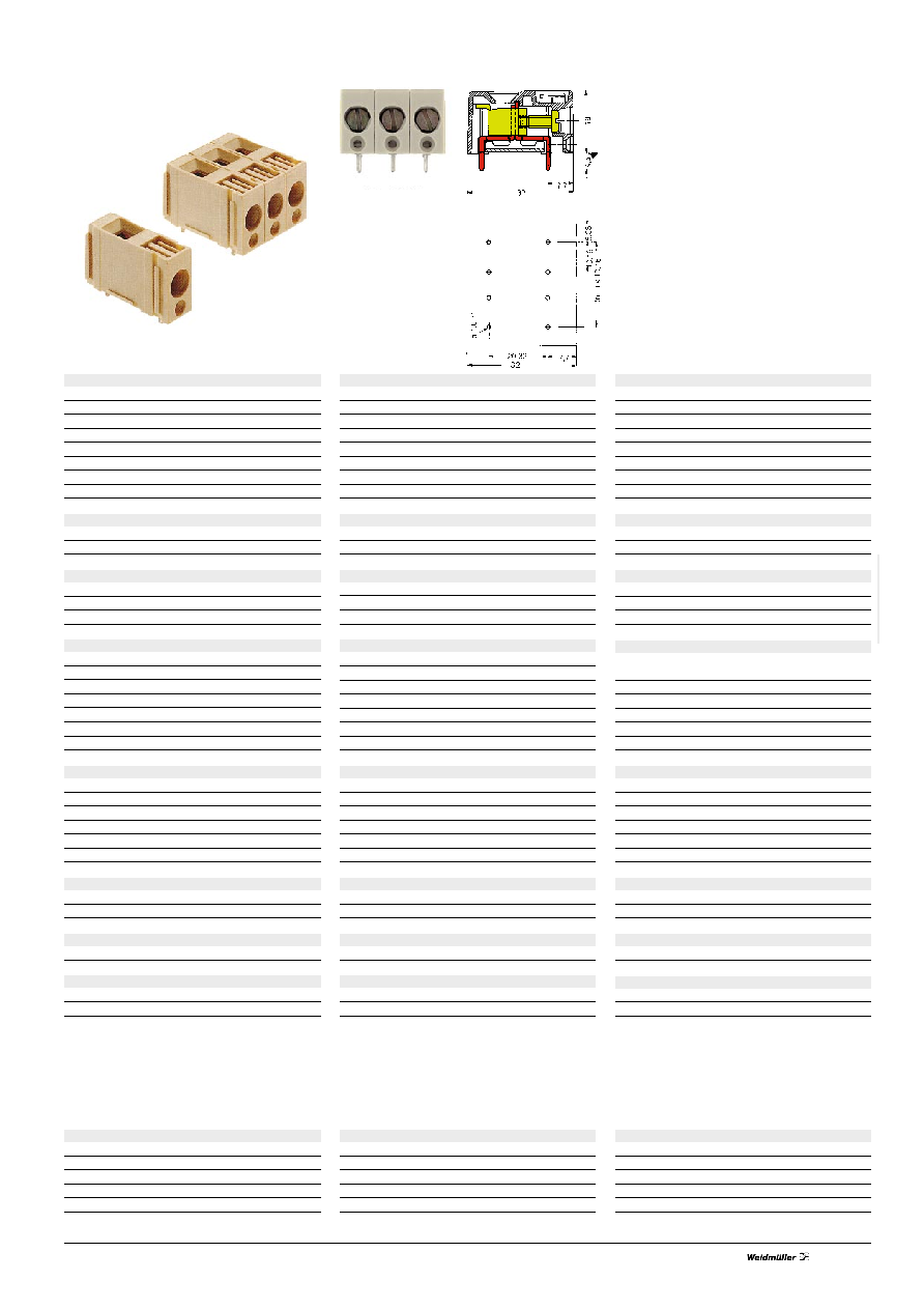
GSE 10
Screw connection max. 10,0 mm2
GSE 10/1 ... 3
Material data
Insulation
Colour
Flammability class
Characteristic system value
Pitch
mm
Mounting hole
mm
Insulation stripping length
mm
Clamping screw
M
Clampable conductors
Max. clamping range
mm2
solid H05(07)V-U
mm2
flexible H05(07)V-K
mm2
with ferrules
to DIN 46228/1
mm2
with plastic collar to DIN 46228/4
mm2
AWG-conductor
Gauge pin to EN 60947-1/7.92
Dimension
VDE rated data
Rated cross-section
mm2
Rated current (Tu = 20 °C)
A
Rated voltage to VDE 0110 1.89
V
Rated impulse voltage
kV
Pollution severity
Test voltage
kV~
Test torque/Rated torque
Nm
UL rated data
Rated voltage, industriel
V
Rated current
A
Conductor sizes
Tightening torque
Screwdriver Type SD/SDI***
Approvals
For the mounting of PCBs, it should be noted that the rate
data given in the catalogue relate only to the connection ele-
ments. The necessary creepage and clearance paths must be
observed in connection with the respective application in
accordance with VDE 0110.
The current-carrying capacity of PCBs is to be determined
according to DIN IEC 326 Part 3 .
Accessories
Test plug
Marking material**
Pitch 10,16 mm
Solder pin length 4,5 mm
No. of poles
Type
Cat.No.
Qty.
1
GSE 10/1
047870
50
3
GSE 10/3
047890
20
4
GSE 10/4
161022
20
Other numbers of poles on request
PA 66
grey*
UL 94 V2
10,16
1,6 +0,1
10
4
0,33…10
0,5…10
0,75…4
22…8
A 5
6
46
400
6
3
2.5
1,2
300
10
22 ... 8
List on request
One-pole GSE terminal blocks can be jointed together to form
terminal strips of up to 10 poles.
Type
Cat.No.
Qty.
PS 2.0
031000
20
DEK 5
047346
500
* Other colours on request
** See section 8/markers for other versions
*** See section 9/tools for other versions
相关PDF资料 |
PDF描述 |
|---|---|
| 151626 | HEADER PCB HORZ 15WAY |
| 160447 | STIFTLEISTE VERT GESCHL 2POL |
| 160448 | STIFTLEISTE VERT GESCHL 3POL |
| 160449 | STIFTLEISTE VERT GESCHL 4POL |
| 160450 | STIFTLEISTE VERT GESCHL 5POL |
相关代理商/技术参数 |
参数描述 |
|---|---|
| 1516160000 | 功能描述:CONN HDR 5.08MM 14POS 90 ORG RoHS:是 类别:连接器,互连式 >> 接线座 - 接头,插头和插口 系列:Omnimate SL 标准包装:1 系列:OSTE2 端接块类型:插头,母插口 每电平位置:17 间距:0.138"(3.50mm) 级别数目:1 接头定向:- 插头导线入口:180° 端子:螺钉 线规:14-28 AWG 电流:10A 电压:300V 安装类型:自由悬挂 特点:- 颜色:黑 包装:散装 |
| 1-516162-3 | 制造商:TE Connectivity 功能描述:FUEHRUNG - Bulk |
| 1516166 | 制造商:Phoenix Contact 功能描述:SACB 10-3 L M8 PUR/ |
| 151617-000 | 制造商:TE Connectivity 功能描述:55PC0811-14-9CS2637 - Cable Rools/Shrink Tubing |
| 1516179 | 制造商:Phoenix Contact 功能描述:SACB 8-4 L M8 PUR/ |
发布紧急采购,3分钟左右您将得到回复。