- 您现在的位置:买卖IC网 > PDF目录222090 > 1339-2DVGI (INTEGRATED DEVICE TECHNOLOGY INC) 1 TIMER(S), REAL TIME CLOCK, PDSO8 PDF资料下载
参数资料
| 型号: | 1339-2DVGI |
| 厂商: | INTEGRATED DEVICE TECHNOLOGY INC |
| 元件分类: | 时钟/数据恢复及定时提取 |
| 英文描述: | 1 TIMER(S), REAL TIME CLOCK, PDSO8 |
| 封装: | 3 MM, ROHS COMPLIANT, MSOP-8 |
| 文件页数: | 26/26页 |
| 文件大小: | 330K |
| 代理商: | 1339-2DVGI |
IDT1339
REAL-TIME CLOCK WITH SERIAL I2C INTERFACE
RTC
IDT
REAL-TIME CLOCK WITH SERIAL I2C INTERFACE
9
IDT1339
REV N 060311
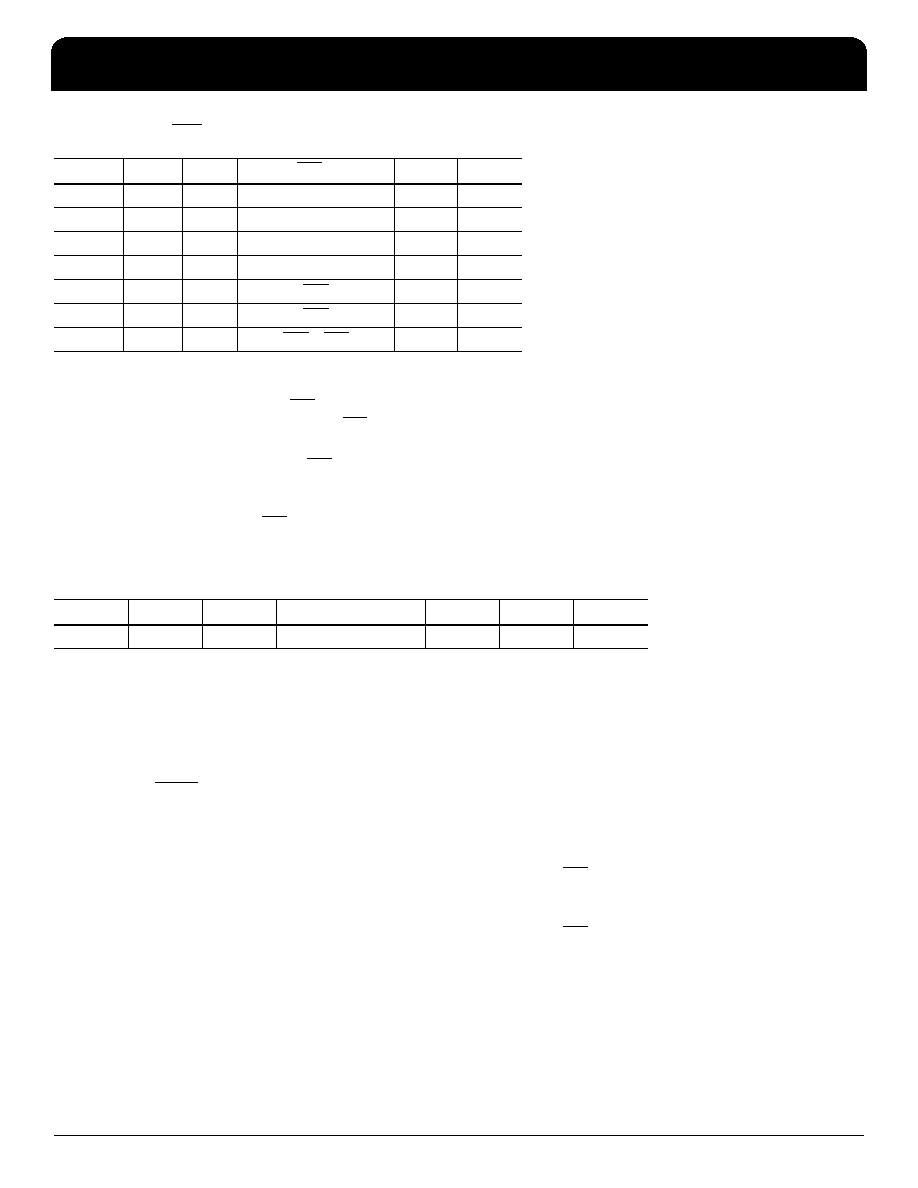
Table 5. SQW/INT Output
Bit 2: Interrupt Control (INTCN). This bit controls the relationship between the two alarms and the interrupt output
pins. When the INTCN bit is set to logic 1, a match between the timekeeping registers and the alarm 1 or alarm 2
registers activate the SQW/INT pin (provided that the alarm is enabled). When the INTCN bit is set to logic 0, a
square wave is output on the SQW/INT pin. This bit is set to logic 0 when power is first applied.
Bit 1: Alarm 2 Interrupt Enable (A2IE). When set to a logic 1, this bit permits the Alarm 2 Flag (A2F) bit in the
status register to assert SQW/INT (when INTCN = 1). When the A2IE bit is set to logic 0 or INTCN is set to logic 0,
the A2F bit does not initiate an interrupt signal. The A2IE bit is disabled (logic 0) when power is first applied.
Bit 0: Alarm 1 Interrupt Enable (A1IE). When set to logic 1, this bit permits the Alarm 1 Flag (A1F) bit in the status
register to assert SQW/INT (when INTCN = 1). When the A1IE bit is set to logic 0 or INTCN is set to logic 0, the A1F
bit does not initiate an interrupt signal. The A1IE bit is disabled (logic 0) when power is first applied.
Status Register (0Fh)
Bit 7: Oscillator Stop Flag (OSF). A logic 1 in this bit indicates that the oscillator either is stopped or was stopped
for some period of time and may be used to judge the validity of the clock and date data. This bit is edge triggered
and is set to logic 1 when the oscillator stops. The following are examples of conditions that can cause the OSF bit
to be set:
1) The first time power is applied.
2) The voltage on both VCC and VBACKUP are insufficient to support oscillation.
3) The EOSC bit is turned off.
4) External influences on the crystal (e.g., noise, leakage, etc.).
This bit remains at logic 1 until written to logic 0. This bit can only be written to a logic 0.
Bit 1: Alarm 2 Flag (A2F). A logic 1 in the Alarm 2 Flag bit indicates that the time matched the alarm 2 registers. If
the A2IE bit is a logic 1 and the INTCN bit is set to a logic 1, the SQW/INT pin is also asserted. A2F is cleared when
written to logic 0. This bit can only be written to logic 0. Attempting to write to logic 1 leaves the value unchanged.
Bit 0: Alarm 1 Flag (A1F). A logic 1 in the Alarm 1 Flag bit indicates that the time matched the alarm 1 registers. If
the A1IE bit is a logic 1 and the INTCN bit is set to a logic 1, the SQW/INT pin is also asserted. A1F is cleared when
written to logic 0. This bit can only be written to logic 0. Attempting to write to logic 1 leaves the value unchanged.
INTCN
RS2
RS1
SQW/INT Output
A2IE
A1IE
00
0
1 Hz
X
0
1
4.096 kHz
X
0
1
0
8.192 kHz
X
0
1
32.768 kHz
X
1X
X
A1F
01
1X
X
A2F
10
1X
X
A2F + A1F
11
Bit 7
Bit 6
Bit 5
Bit 4
Bit 3
Bit 2
Bit 1
Bit 0
OSF
00000
A2F
A1F
相关PDF资料 |
PDF描述 |
|---|---|
| 1339-31DCGI8 | 1 TIMER(S), REAL TIME CLOCK, PDSO8 |
| 13715-806-XTD | 300 MHz, OTHER CLOCK GENERATOR, PDSO16 |
| 1374610-3 | INTERCONNECTION DEVICE |
| 1376137-1 | POWER CONNECTOR |
| 1380B-8 | BRASS, GOLD FINISH, PCB TERMINAL |
相关代理商/技术参数 |
参数描述 |
|---|---|
| 1339-2DVGI8 | 功能描述:实时时钟 RTC BASE RoHS:否 制造商:Microchip Technology 功能:Clock, Calendar. Alarm RTC 总线接口:I2C 日期格式:DW:DM:M:Y 时间格式:HH:MM:SS RTC 存储容量:64 B 电源电压-最大:5.5 V 电源电压-最小:1.8 V 最大工作温度:+ 85 C 最小工作温度: 安装风格:Through Hole 封装 / 箱体:PDIP-8 封装:Tube |
| 13393 | 制造商:Desco Industries Inc 功能描述:BG STSHLD MTL-IN 16''X30'' 100EA |
| 1339-3/4"x60yd | 功能描述:胶带 1339 TAPE 3/4X60YDS BULK 3" PAPER CORE RoHS:否 制造商:3M Electronic Specialty 产品:Tapes 类型:Shielding 描述/功能:EMI/RFI Foil Shielding Tape 颜色: 材料:Copper Foil 宽度:1 in x 18 yds |
| 1339-3/4INX60YDS | 制造商:3M Electronic Products Division 功能描述:80008005862 |
| 1339-3/8"x60yd | 功能描述:胶带 TAPE 3/8 INX60YD BULK 3"CORE RoHS:否 制造商:3M Electronic Specialty 产品:Tapes 类型:Shielding 描述/功能:EMI/RFI Foil Shielding Tape 颜色: 材料:Copper Foil 宽度:1 in x 18 yds |
发布紧急采购,3分钟左右您将得到回复。